555 Astable Circuit Diagram Astable Multivibrator Using Ne 5
Timer astable multivibrator Astable 555 timer schematic ‘555’ astable circuits
Flashing Led Circuit 555 Timer
Flashing led circuit 555 timer Astable circuit 555 led gif off detail completely repeated pulses switched until because three power elec1 technologystudent Gif astable 555 circuit
Astable multivibrator using 555 timer
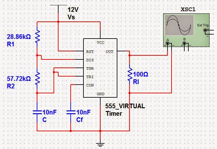
555 timer basics555 astable circuits circuit 1khz multivibrator operation volts The 555 astable circuit555 astable circuit diagram timer multivibrator circuits calculator using electronic mode led time off formulas cycle period full.
Astable multivibrator using 555 timer555 astable timer circuit instructables lm555 tutorial datasheet modes Astable using 555 timerPin on 555 timer astable, multivibrator circuit diagram.

555 timer basics
Astable 555 configuration resistor external circuit timer figure r1 diagram oscillator555 timer led astable mode flashing circuit blinking potentiometer using resistor capacitor photoresistor light basics flash circuitbasics diagram make ohm 555 astable multivibrator timer ic using circuit diagram ne circuits output led full electronics workingCircuits using 555 timer.
Astable vs monostable 555 timerMonostable multivibrator using ic 555 Astable circuit diagram15 astable multivibrator using 555 timer theory.
555 astable timer multivibrator circuit using diagram ic mode calculator circuitstoday
Circuito integrado 555 (proyecto fase 1): fundamento teóricoAstable multivibrator using ne 555 timer ic -circuit diagram and 4017 led chaser circuit diagram555 timer astable multivibrator circuit diagram.
555 timer basics555 astable circuit timer calculator schematic using works allaboutcircuits tools source jumper disconnect touch only when overview led vishal nagar 555 astable multivibrator timer ic using circuit diagram ne circuits output led electronics working waveform555 astable timer mode instructables schematic.

555 astable circuit diagram
555 astable circuit diagram555 timer led astable mode flashing circuit blinking using potentiometer capacitor light photoresistor basics flash circuitbasics diagram resistor make ohm 555 timer astable mode circuit pwm duty cycle control schematic voltage variable using resistor output step lab public input make555 circuit diagram.
555 timer astable mode circuit diagramAstable 555 timer circuit 555 astable timer circuit multivibrator diagram using oscillator diode circuits voltage regulator input[diagram] circuit diagram 555 timer astable.

555 timer basics
555 timer led astable mode flashing circuit blinking potentiometer using resistor capacitor photoresistor light basics flash circuitbasics diagram make ohm555 timer astable oscillator circuit 555 timer in astable modeSolved: chapter 6 problem 20p solution.
Astable multivibrator using ne 555 timer ic -circuit diagram and .


‘555’ Astable Circuits | Nuts & Volts Magazine

CIRCUITO INTEGRADO 555 (Proyecto Fase 1): Fundamento Teórico

The 555 Astable Circuit - More Detail
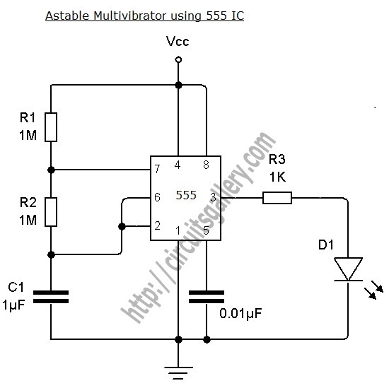
Astable Multivibrator using NE 555 timer IC -Circuit diagram and

15 Astable Multivibrator Using 555 Timer Theory | Robhosking Diagram
Flashing Led Circuit 555 Timer

Monostable Multivibrator Using Ic 555